Search

FAH54

FAH54

FAH54

  • Typical application areas: shipbuilding (e.g., drive shafts and flywheels)

  • Frequency detection on ferromagnetic scanning objects according to the Hall principle

  • Protection rating: IP68 (5 bar)

  • Robust design with high resistance to vibration and shock

  • Straight or lateral cable exit, available with cable protection system

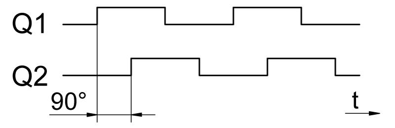
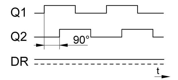
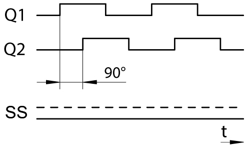
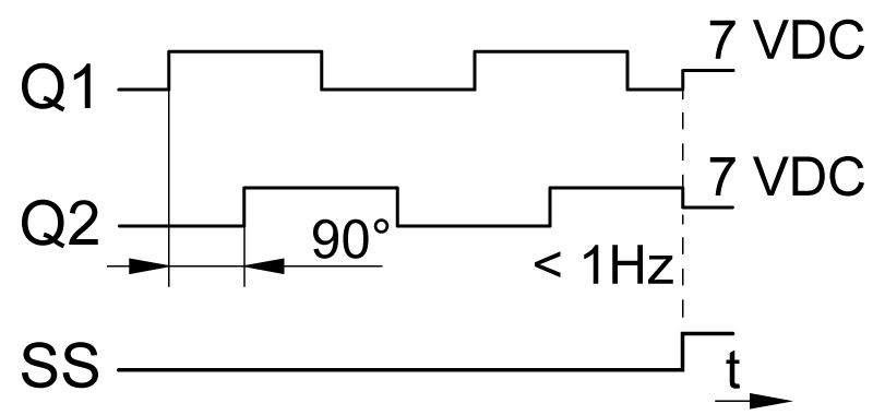
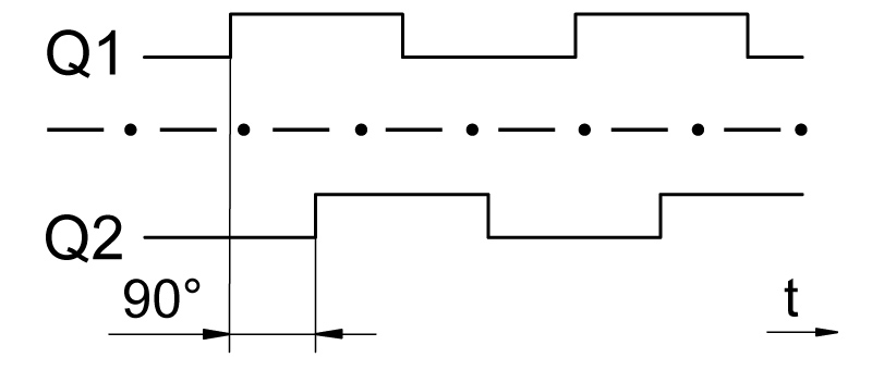
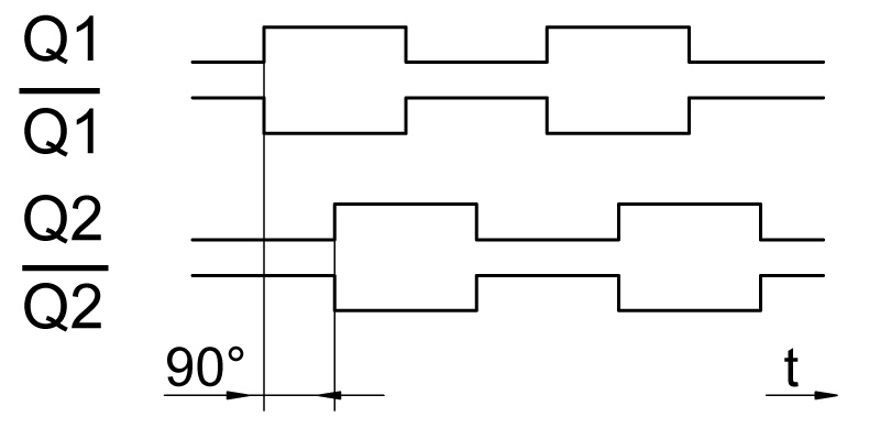
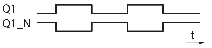
  • Up to four output signals, on request as a version with a status signal for rotational direction detection, on request two galvanically isolated output signals

Speed sensors type series FA54 are compact and robust flange sensors with common approvals for the shipbuilding industry. They are suitable for scanning ferromagnetic objects, such as toothed wheels, bolt heads, bore holes, gaps, grooves or pulse bands.

The different sensor variants allow measurements with up to two measuring channels and up to four output signals for measurement of frequencies from 0 to 20 kHz. This makes them suitable for standstill detection and for rotational direction detection by using phase shifted signals. Different sensor tube lengths and connection outlets as well as your tailor-made solution on request enable an adaptation to almost any application. Do not hesitate to contact our technical sales team (sales@noris-group.com) and ask for a quotation.

Overview of FAH54 signal outputs

Type

Measuring principle

Signal outputs

Signal waveform

FAH54

Hall

One square wave signal

Signalform FAx1x_Q1

FAHZ54

Hall

Two square wave signals,
Q2 to Q1 phase shift by 90°

FAxZ Phasendiagramm

FAHS54 *

Hall

Two square wave signals,
Q2 to Q1 phase shift by 90°,
one status signal

Direction of rotation:
FAxS_Drehrichtung Phasendiagramm
Standstill (on request):
FAxS_Stillstand Phasendiagramm
Standstill (on request):
FAxS_7V Stillstand Phasendiagramm Mittelspannun und Stillstandssignal

FAHD54

Hall

Two galvanically isolated square wave signals,
Q2 to Q1 phase shift by 90°

FAxD Phasendiagramm galvanisch getrennt

FAHQ54

Hall

Two + two inverted square wave signals,
Q1 to Q2 and Q1_N to Q2_N phase shift by 90°

FAxQ Phasendiagramm

FAHY54

Hall

Two square wave signals, Q1_N inverted to Q1

FAxY Phasendiagramm

* Type -S: Approval for marine application on request

FA54 – Approvals

Approvals

Logo_Klasse_ABS

Logo_Klasse_BV

Logo DNV

Logo_Klasse_LR

Supply voltage UB

9 ... 32 VDC

Frequency range

0 ... 20,000 Hz

Measuring channels

Depending on the sensor type( cf. description)

Output signals and signal form

1 square wave signal or
2 square wave signals or
1 square wave signal, 1 inverted square wave signal or
2 square wave signals, 1 status signal or
2 square wave signals, 2 inverted square wave signals

Scanning object

Ferromagnetic materials

Distance scan object

0.2 ... 3 mm; recommended: 1.0 ± 0.5 mm

Operating temperature

-40 … +120°C

Degree of protection

Housing: IP66/IP68
Connection: IP66/IP68

Type code structure

FA

H

Z

54-

11-

S

X

07-

M30-

S0

Example: FAHZ54-11-SX07-M30-S0

Measuring principle

Measuring principle supplement

Construction type and material

Nominal length L1 of the sensor tube

Connection outlet

Electrical connection

Sheath length

Module

Shield / Addition

FAH[..]54 part code

Measuring principle

H

Hall

Measuring principle extension

No identifier: 1 Output signal

Z

2 Output signal (voltage), galvanic coupling

D

2 Output signal (voltage), galvanically isolated

Y

2 Output signals (current), galvanic coupling, second signal inverted

S

2 Output signal (voltage), galvanic coupling with
status output (e.g. rotational direction detection, desired definition on request)

Q

4 Output signal (voltage), galvanic coupling

Model and material

54-

Flange, stainless steel sensor tube

Nominal length

11-

L1 = 29 mm

12-

L1 = 57 mm

13-

L1 = 32.2 mm

14-

L1 = 44.5 mm

15-

L1 = 34.5 mm

More lengths on request

Connection outlet

No identifier: straight connection outlet

S

Lateral connection outlet

R

90° angled connection outlet

Electrical
connection

X

Standard cable end (without protective tube)

Jacket length

05-

Jacket length 2.0 m, halogen-free

07-

Jacket length 5.0 m, halogen-free

08-

Jacket length 7.5 m, halogen-free

09-

Jacket length 10.0 m, halogen-free

Module

M10-

Module m1

M12-

Module m1.25

M15-

Module m1.5

No identifier: Module m2

M25-

Module m2.5

M30-

Module m3

Shielding

No identifier: Shield applied to sensor housing

S0

Shield applied to sensor housing

FA

_ _

_ _

_ _-

_ _-

_ _

_ _

_ _-

_ _-

_ _

Example:
FAHZ54-11-X07